Interrupt-Driven Reverse Geocache Box
A project to help my best friend propose to their (now) wife.
Overview
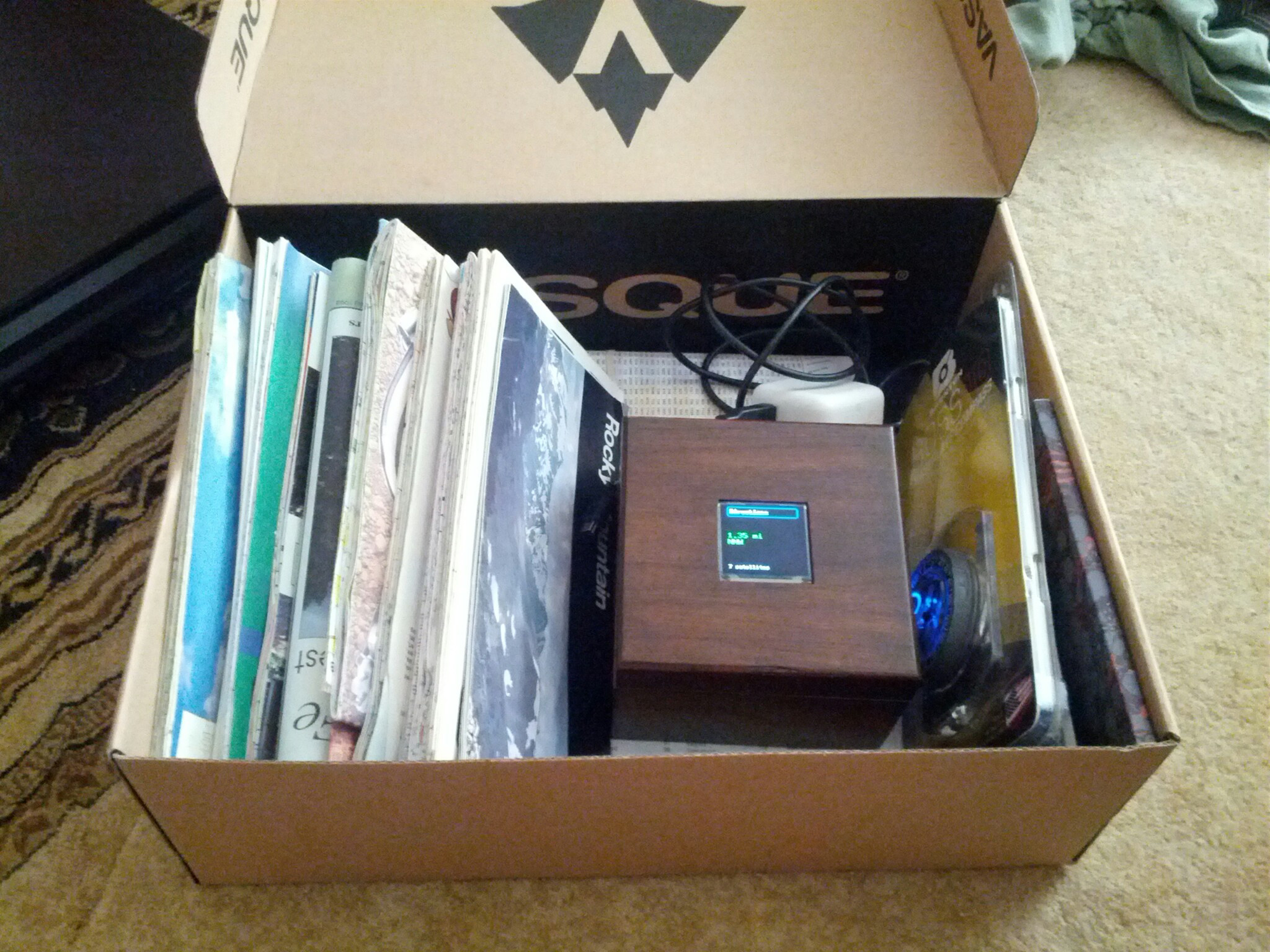
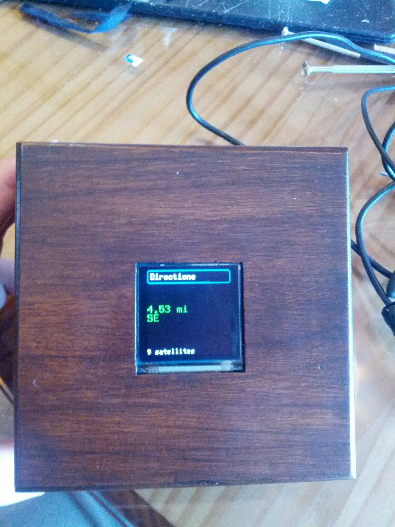
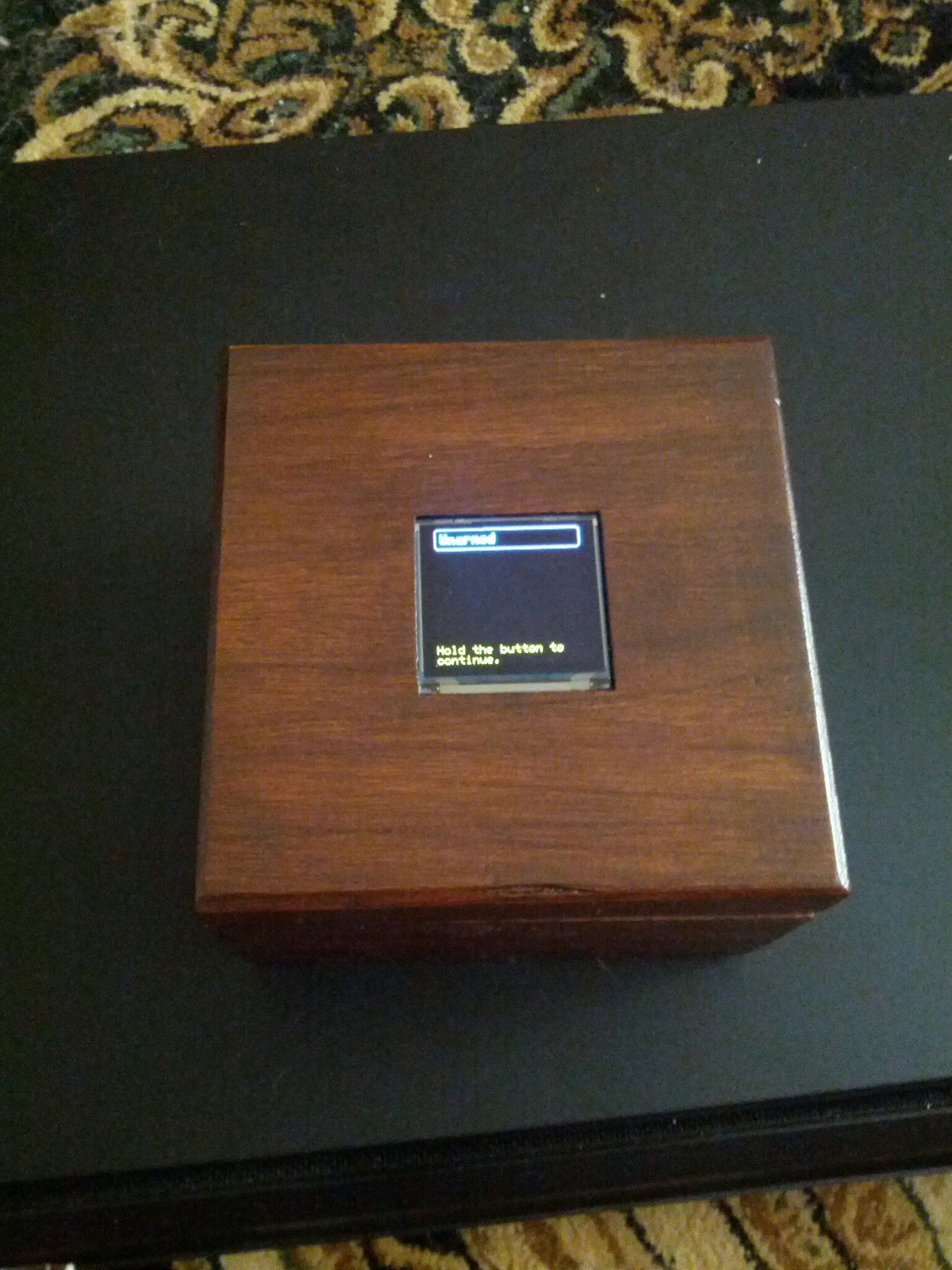
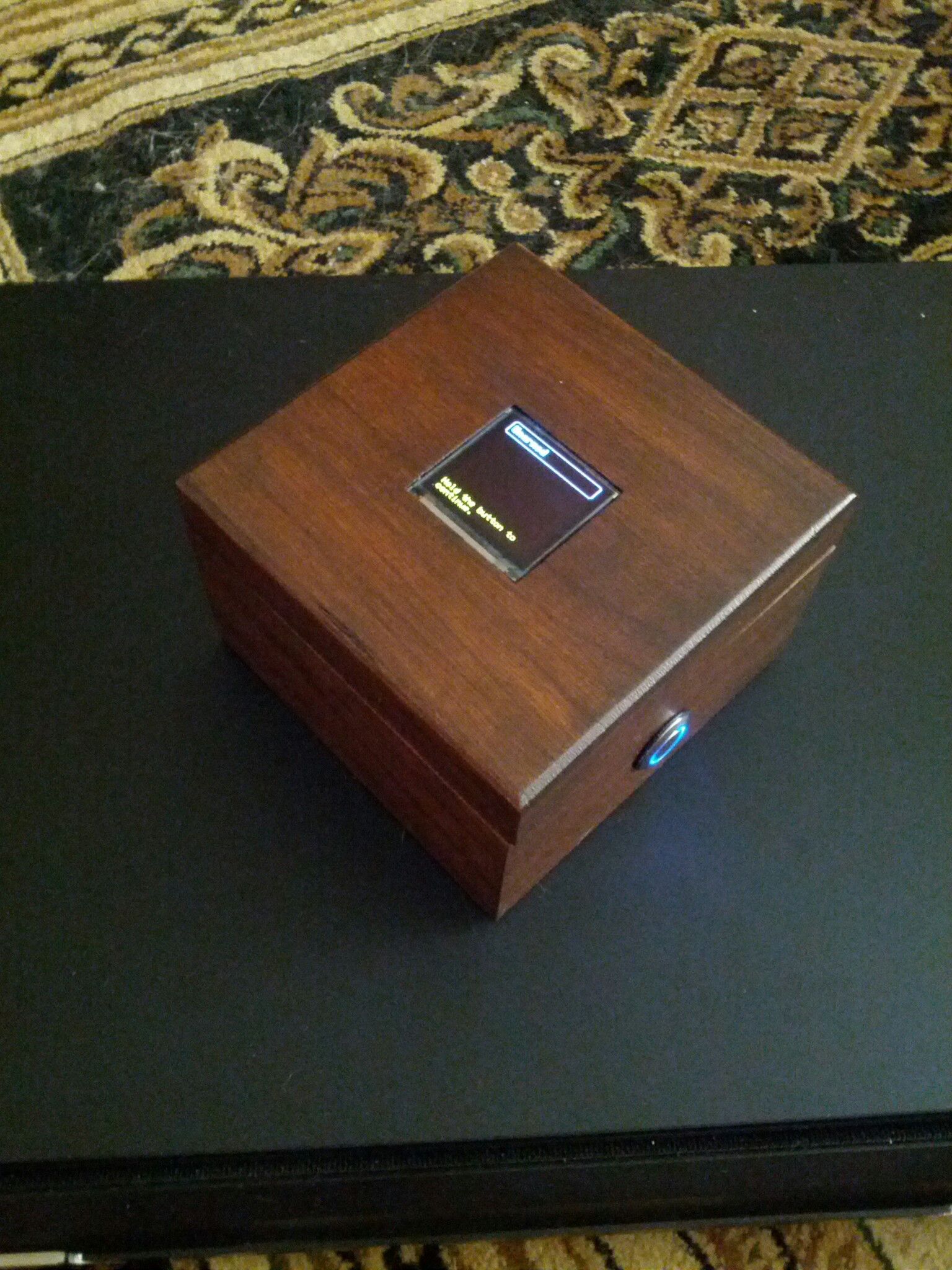
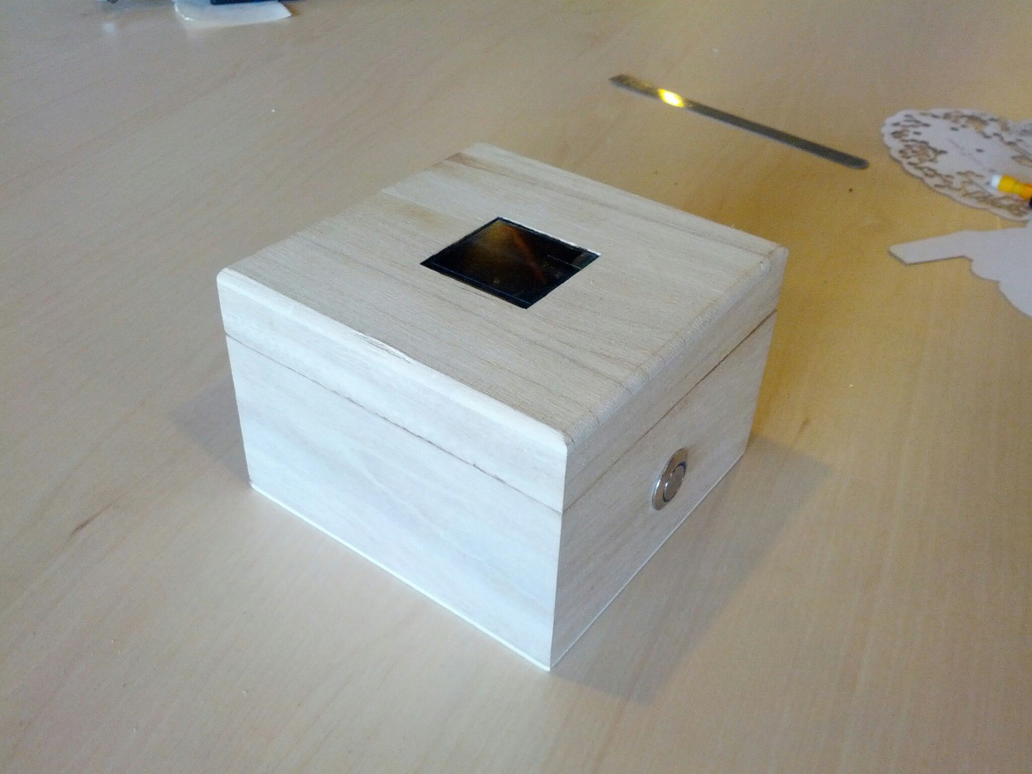
What is a reverse geocache box, you say? In the simplest of terms, it's like a regular geocache, except you start with the cache locked in a box that is location aware (it has a GPS). You take the box to the appropriate location and it will open up! How do you know what location to take it to, you ask? There is a screen on the top of the box which tells you what direction to go and how far to go in that direction. It's probably best to bring some maps with you or use Google Maps to try to determine where you really need to go as it only gives you simple distance and direction. Sounds cool, huh?
Features
Oh, you've seen projects like this before? What's so special about our box? Excellent question! We decided to take it a couple steps further. First, we chose to handle power conservation a bit differently. Second, the box doesn't just open when you get to a single designated location. Its firmware allows for multiple locations to be set and the box only opens once you have visited each location in order. I know what you're thinking, it sounds like more trouble than it's worth. Well, there's a reason for all of the different locations. The box is to be used in a wedding proposal. The idea is to revisit some of the important memories of their courtship.
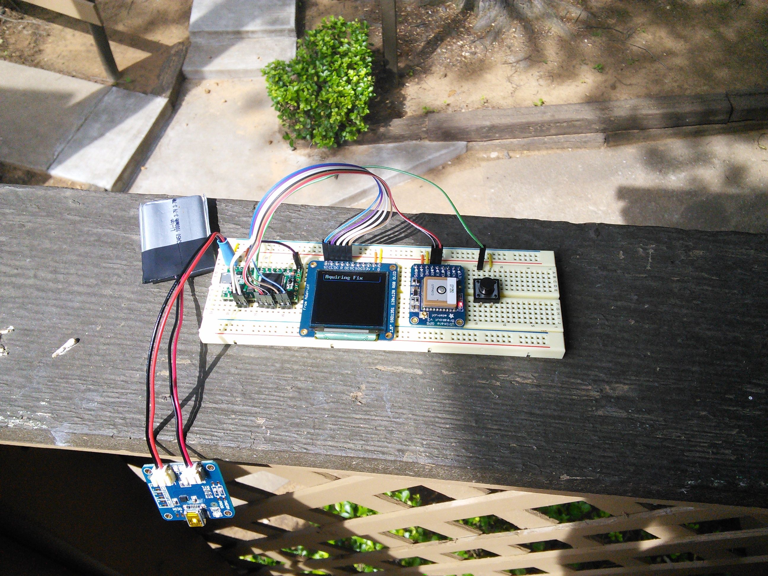
So, what about the "interrupt-driven" part? All the other RGB projects I've seen use a Pololu switch to cut power to the MCU. While that is extremely effective, it's also kind of boring. Our box uses low power modules with sleep functions to reduce their power consumption when not in use. We use a hardware interrupt on the MCU to wake it up and then it wakes up the other modules. It also sports a USB charging circuit so that the 2500mAh battery can be charged and is ready when you need it.
Parts
- Teensy 3.1
- Adafruit Ultimate GPS Breakout
- 1.5" Color OLED
- Lithium Ion Polymer Battery - 3.7v 2500mAh
- USB LiIon/LiPoly charger
- Micro Servo
- Waterproof Metal Pushbutton with Blue LED Ring
- Large Enclosed Piezo Element w/Wires
- 3 x NDS355AN N-Channel MOSFET
- 3 x 330Ω Resistors
- 3 x 100kΩ Resistors
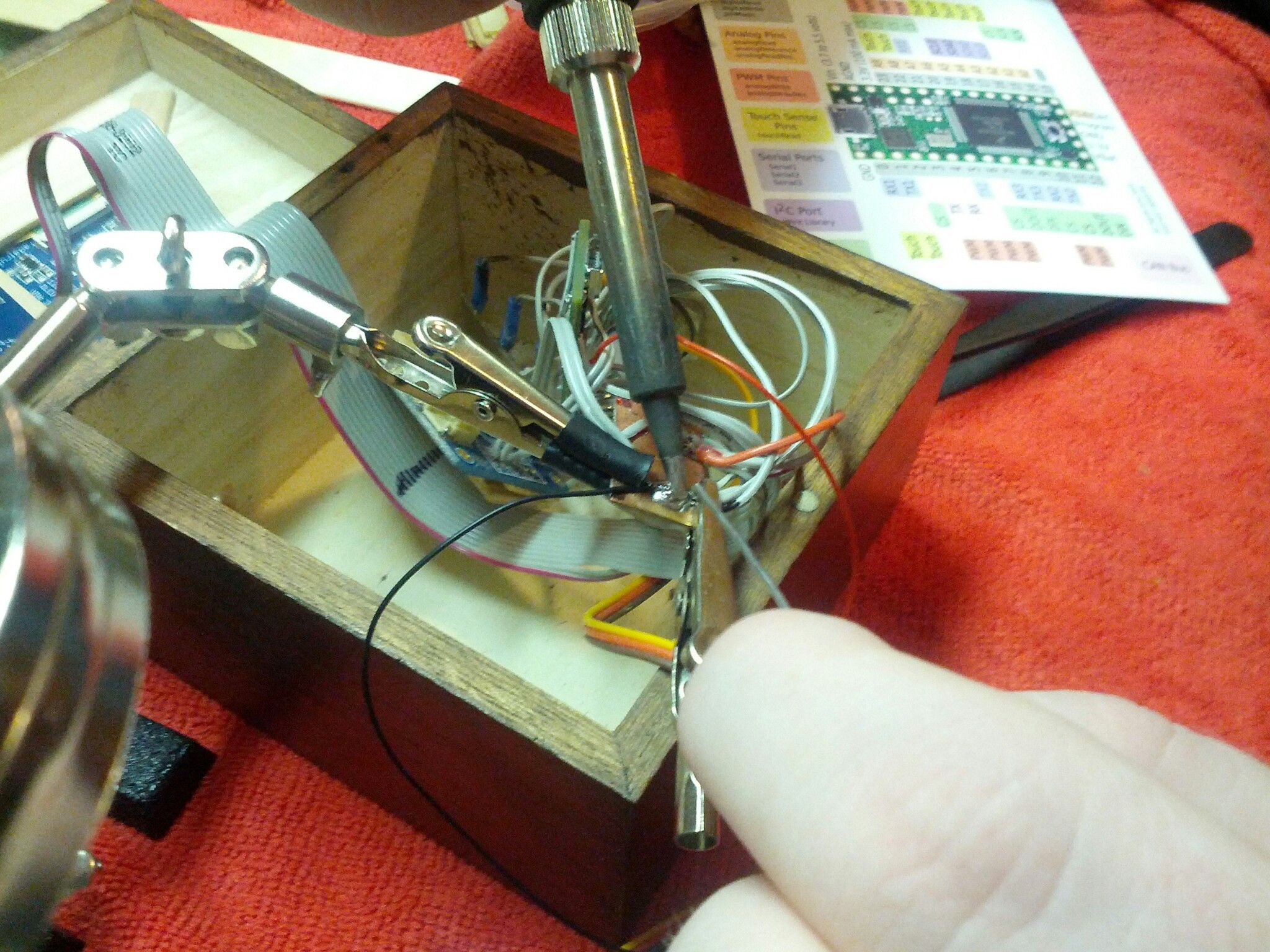
Tools & Supplies
- Soldering Iron + Solder
- Ribbon Cable
- Helping Third Hands / Panavise
- Heat Shrink
- Wire Stripper / Cutters
- Glue / Mounting Tack
- Filing Tool / Hobby Knife
Circuit Diagram
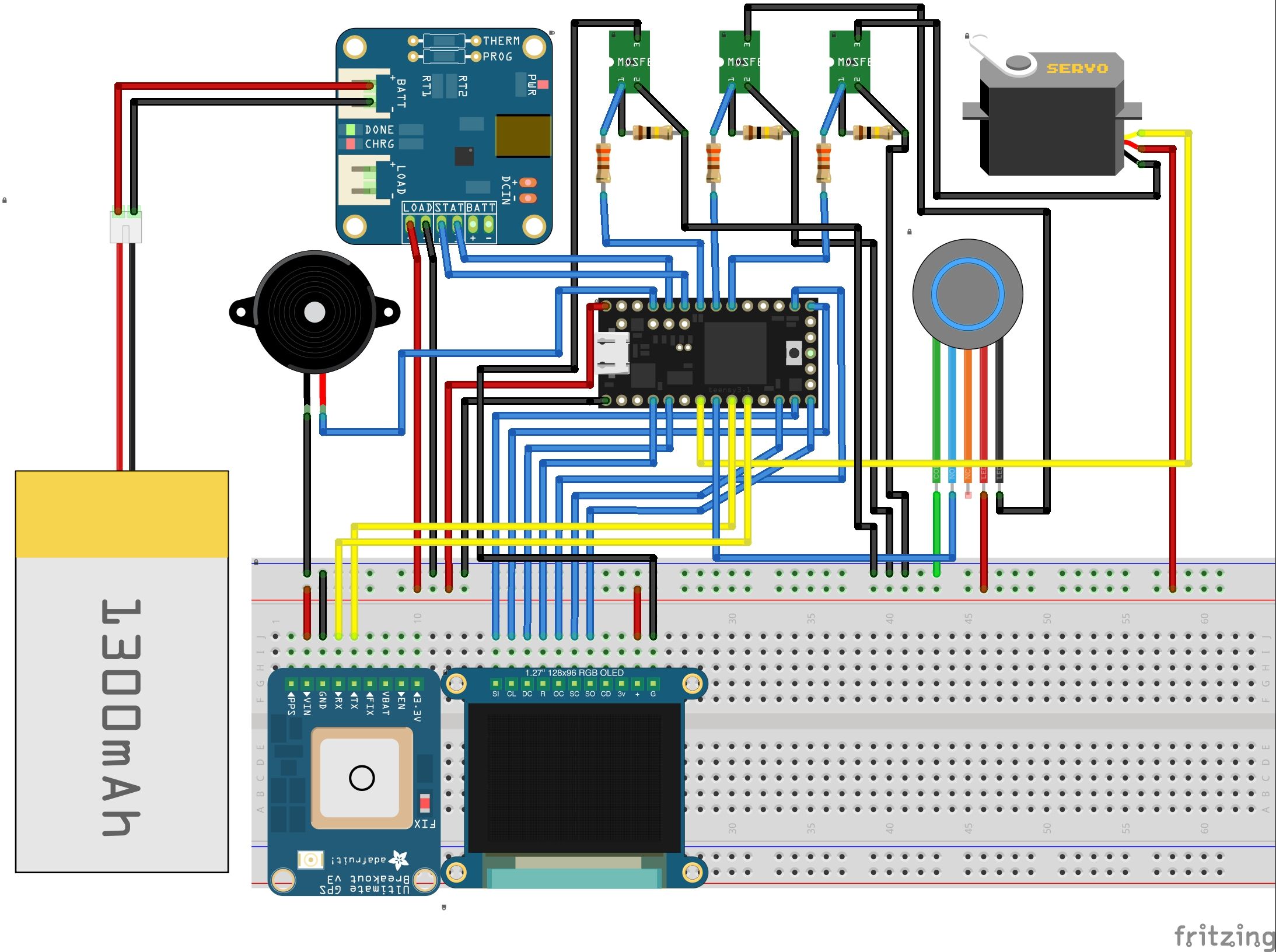
Pins
#define OLED_MOSI       11
#define OLED_CLK        13
#define OLED_CS         14
#define OLED_DC         3
#define OLED_RESET      2
#define SD_MISO         12
#define SD_CS           10
#define PIEZO_PIN       23
#define BUTTON_PIN      6
#define SERVOSIGNAL_PIN 5
#define STATUS1_PIN     22
#define STATUS2_PIN     21
#define OLEDPOWER_PIN   20
#define BUTTONLED_PIN   19
#define SERVOPOWER_PIN  18
Software
All the code used in this project is available on my GitHub.
Conclusion
We did a lot of testing with the prototype, but very little with the actual box, since we ran out of time. However, the box was deployed quite successfully. The GPS and firmware worked flawlessly across 3 states and it locked and unlocked as/when expected.

Authors & Contributors
TJ Peden (tjpeden) designed and developed the electronics. Lora Reames (lora-reames) designed, planned and deployed the project. Special thanks to Andrew Harmon over at FabLab Tulsa for all of his help.